|

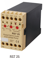
The electronic phase relay RST 25 offers phase, philure shift, phase flashing, asymmetric, Phase sequence and
also under and overvoltage control.

The RST 25 can be connected as following in the installation diagram:
FIG1: connection of the relay before operation.
When the relay is connected as in FIG 1, the there yellow LED’ sL1, L2 and L3 light up when
The power supply A1 phase L, the A2 Neutral, and the three phases “L1”, “L2”and “L3”are connected.
If there is no under or overvoltage, phase failure or phase sequence, the green LED lights up, (terminals 11 and 14 are closed )and the relay is ready for self retaining.
It is also possible to connect the power supply after operation in FIG2.
By both FIG’ s 1 and 2, the terminal “PE” must be grounded.

The desired undervoltage limit can be adjusted down to-25ÔºÖ UN.

The adjusting over-and undervoltage limit, the asymmetric limit is slso adjusted.

The switch off time can be adjusted by the potentiometer “Time Delay” from 0.1……5 seconds. With this
function it is possible to adjust the time for the identification of the failure.

If a phase fails during operation at load or one of the contacts of the contactor or circuit Breaker is defective,(contact bounce or scorched contacts), RST 25 recognizes the failure, And also the feedback voltage, and switches off depending on the setting of “Time Delay”. The RST 25 controls the phase shift. If there is a phase failure the angle from the feedback Voltage is 30°. The RST 25 recognizes this failure.
|